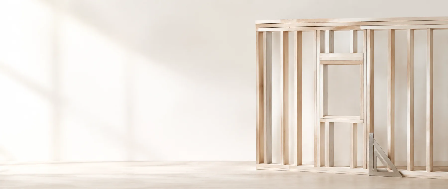
Framing Calculator
Build a transparent wall-stud and plate takeoff from your chosen layout spacing while keeping openings and corner details as explicit allowances.
- Layout studs
- 16
- Opening / corner extras
- 10
- Studs with allowance
- 29
- Plate length
- 60 ft
- Minimum plate stock pieces
- 5 × 12 ft
This is a quantity takeoff from your chosen spacing and detail allowances. It does not size members or design bearing walls, headers, bracing, connections, or openings.
Show calculation
layout = ceil(240 in ÷ 16 in) + 1 = 16; ceil[(16 + 10 extras) × 1.1] = 29 studsTransparent method and editable product assumptions. Verify current labels and project requirements.
How this calculator works
The base wall-stud layout divides wall length by the selected on-center spacing, rounds up so no bay exceeds that spacing, and adds one final end stud. This is a material count from an already chosen layout—not a spacing recommendation.
Opening and corner details vary by the approved assembly. The calculator therefore multiplies the number of openings by your entered extra-stud allowance and adds a separate corner/end quantity instead of pretending every wall uses the same header, king-stud, jack-stud, or cripple-stud pattern.
Plate linear footage equals wall length times the entered number of plate rows. Stock pieces are a minimum linear-foot conversion; actual lap locations, splice support, treated bottom plates, blocking, headers, fire stops, bracing, and cut optimization require the framing plan.
Formula
Studs = ceil{[ceil(wall length ÷ spacing) + 1 + opening extras + corner/end extras] × (1 + allowance)}The live substitution appears with your result.Control example: 20 ft wall at 16 in on center
ceil(240 ÷ 16) + 1 gives 16 layout studs. Two openings at four extra studs each plus two corner/end extras produce 26 studs before allowance.
With 10% allowance, ceil(26 × 1.10) = 29 studs. Three plate rows require 60 linear feet, or at least five 12 ft stock pieces.
Assumptions and limits
- Wall length follows one straight wall line.
- Stud spacing has already been selected for the applicable loads, height, assembly, and code.
- Opening and corner extras come from the project framing detail.
- Plate stock can be allocated across rows subject to approved splice locations.
Common measuring mistakes
- Using this quantity calculator to choose structural stud size or spacing.
- Subtracting the full opening width from base layout studs before adding the approved opening detail.
- Forgetting doubled top plates or a treated bottom plate where specified.
- Treating minimum linear-foot plate pieces as a splice-ready cut list.
Sources
Product-specific values remain editable. These sources support the method and stated examples; they are not a universal substitute for your supplier’s current label.
- American Wood Council Code Conforming Wood Design Explains that stud size, height, spacing, bearing use, top plates, and bottom plates are code- and assembly-dependent.
- American Wood Council calculator help Shows why structural member selection depends on loads, species, grade, spacing, bending, deflection, shear, and bearing.
Questions people ask
How many studs do I need for a wall?
For one straight wall, divide length by the chosen on-center spacing, round up, add the final end stud, then add opening and corner details from the framing plan.
How many 2x4 studs are in a 20-foot wall?
At 16 inches on center, the base layout is 16 studs before openings, corners, blocking, and allowance.
Does this wall stud calculator include doors and windows?
Yes, as an explicit extra-stud quantity per opening. The calculator does not design headers or decide king, jack, or cripple requirements.
How many plate rows should I enter?
Enter the assembly shown on the approved plan. A common wall may use one bottom and two top plates, but conditions and codes vary.
Does this calculator size structural framing?
No. It only counts material from dimensions and spacing you provide. Member size, grade, loads, height, bracing, headers, connections, and code require project-specific design.